
Technical Specifications For Laminate Doors For Projects
Aluminum-framed laminate door systems for corporate projects provide durable door solutions designed for heavy use, with defined installation standards and specifications to ensure consistent quality. This content outlines the profile standards, surface treatments, installation principles, and accessory requirements for adjustable aluminum door frames and laminate door leaves, structured as a technical specification. Key evaluation criteria for tender and procurement processes are presented in a format aligned with project team application discipline.
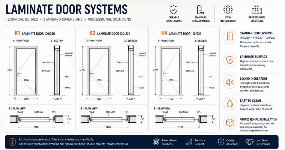
Technical Specification for Aluminum-Framed Laminate Doors (Sample)
1) Scope and Application Principles
This technical specification defines the minimum technical requirements for supplying and installing a system consisting of an adjustable aluminum door frame and a laminate coated door leaf, tailored to project details. Installation must be carried out based on the architectural plans and application details of the building where the work is performed.
All manufacturing related to the door system shall follow approved project documents, detailed drawings, and prescribed quality control procedures. This approach minimizes non-standard installation risks on site, supporting the door's functional lifespan and consistent performance.
2) Adjustable Aluminum Door Frame: Profile Material and Standards
Profiles used in the production of adjustable aluminum door frames must be selected from EN standard A6060 or A6063 alloys, compliant with international norms. Verification of the chemical composition through electronic spectrometer reports is critical to ensure quality and batch consistency.
The aluminum profile raw material should be suitable for extrusion and anodizing (eloxal) processes, enabling both mechanical stability and durable decorative/protective surface integrity.
3) Profile Production Controls and Dimensional Tolerances
Extruded profiles must be evaluated for geometric and surface characteristics including angles, dimensions, radii, squareness, surface quality, curvature, warping, burrs, stacking deformation, and cross-section accuracy. These inspections should be conducted regularly using appropriate measurement methods in accordance with DIN 17615, DIN 1748, and TS 996 standards.
Cooling methods and cold stretching processes during production must achieve the required mechanical properties, and profile length cuts must meet dimensional accuracy. Compliance with DIN 1748 and DIN 17615 standards for design and manufacturing tolerances is essential.
4) Mechanical Properties of Profiles (Minimum Requirements)
The mechanical and physical properties of profiles used in adjustable aluminum door frames are crucial for project performance and service life. The minimum requirements are as follows:
- Density: 2.7 g/cm3;
- Elastic Modulus: 7000 Kg/mm2;
- Melting Point: 600 – 650 °C;
- Thermal Expansion Coefficient: 23 × 10-6 m/°C;
- Tensile Strength: 215 N/mm2;
- Yield Strength: 160 N/mm2;
- Elongation at Break (A5): 12%;
- Elongation at Break (A10): 10%;
- Hardness (Brinell): 70;
- Standard: DIN 1748 Part 1 (TS 996)
Aluminum profiles must have a "TSE Quality Certificate," and manufacturing facilities must hold "TSE Manufacturing Competency Certificates" and ISO 9002 quality assurance certificates. These documents are fundamental references for procurement and acceptance in corporate projects.
5) Surface Treatment: Anodizing (Eloxal)
All anodizing processes must comply with TS 4922, BS 1615, and DIN 17611 standards. The anodized layer provides not only decorative color but also enhanced surface stability against environmental effects.
Anodizing Thickness and Color Approval
The anodized layer thickness must be at least 18–20 microns in accordance with TS 4922. Color selection should be finalized based on the project architect and client preferences, with production proceeding only after color approval.
6) Installation: Load-Bearing Frame Design and Application Criteria
The load-bearing frame must securely support hinge loads, door opening and closing impacts, and door leaf weight throughout its service life. The main load-bearing surface thickness should be no less than 1.8 mm, with other frame areas having a minimum thickness of 1.5 mm.
The frame must include a channel for attaching the trim profile, allowing 25 mm of adjustment movement. This channel also supports a cushioning system component that facilitates smooth door leaf operation. Designing the weatherstrip to be externally attachable enables easy maintenance and replacement.
Frame Geometry and Connection Logic
The visible outer surface of the frame should be at least 55 mm, with the wall-covering part designed at 30 mm. Without weatherstripping, a 47 mm door leaf clearance is required; with weatherstripping, this clearance is 45 mm. Connector elements should have clearance spaces of 20 mm on the short side and 50 mm on the long side to ensure corner stability.
Main load-bearing and connecting brackets must be fastened to the frame on both sides using two smart screws each. Auxiliary load-bearing and connecting bracket channels should be present and reinforced by driving screws with a screwdriver.
Frame Installation and Prohibited Practices
The frame must be installed by screwing it into the wall using blind frames or wooden shims, with dedicated aluminum ears or protrusions on the frame for this purpose. Weatherstrip adhesive extensions should be integrated into the design, and installation must involve bonding the weatherstrip to these extensions.
Mounting the frame and trims solely by compression or foam filling is not acceptable, as such methods can lead to sagging and gap issues over time.
7) Trim: Application and Adjustment Capability
The trim must include weatherstrip adhesive extensions on surfaces contacting the wall, with installation based on weatherstrip-supported mounting principles. The visible outer surface of the trim should be at least 50 mm.
The trim's extension connecting to the frame must have auxiliary load-bearing and connecting bracket channels, with connections secured by smart screws or pop rivets. The wall-covering section should have two channels, reinforced by driving screws with a screwdriver.
Trim Dimensions
Trim profiles must be at least 60 mm wide and designed to be adjustable for different wall thicknesses, facilitating practical management of wall tolerances on site.
8) Brackets: Load-Bearing and Connecting Components
Brackets within the system are critical for enhancing stability at frame and trim joints. Main load-bearing and connecting brackets must have minimum dimensions of 20 mm (short side) by 50 mm (long side).
Auxiliary load-bearing and connecting brackets should be made from aluminum sheet, measuring 12 mm in width, 40 mm in length, and 2 mm in thickness. Their connection method must comply with installation standards.
9) Hinges: Durability and Alignment Requirements
The hinge system must ensure the door leaf operates without axis displacement over extended use. To achieve this, hinges must be aligned on the same axis and supported with reinforcement tabs on both the frame and door leaf hinge pins.
Hinge mounting areas must have a minimum thickness of 4 mm; hinge pin diameter should be 10 mm, with a total of 15 mm including the outer aluminum. Pins must be protected with special plastic coatings, and copper washers placed between plastic parts to reduce wear, positively impacting service life.
10) Weatherstripping: Door Operation Comfort and Sealing
Door leaf sealing weatherstrips should be gray silicone-based profiles. Wall weatherstrips must also be gray silicone-based adhesive types. The weatherstrip system stabilizes both operational comfort and door closing performance.
Designing the weatherstrip to be retrofittable allows for easy replacement during maintenance cycles.
11) Door Handles: Quality Standards and Installation Details
Door handles must be selected from internationally recognized manufacturers and made of aluminum casting. Anodized coating can be applied to enhance surface durability if needed.
Handles must include centering pins, with escutcheons screwed together rather than directly attached to support plates or profiles, ensuring installation stability per specification requirements.
12) Laminate Door Leaf: Construction, Core, and Processing
The door leaf must be constructed with a frame system designed per project specifications, using white pine timber with minimum cross-sections of 42 mm × 32 mm. The frame should be filled with at least 32 mm kraft paper core to form the skeleton.
Both sides of the skeleton must be covered with a minimum 4 mm MDF (medium-density fiberboard) and laminated panels bonded securely to the surface. After edge finishing, appropriate edge banding must be applied to ensure surface continuity and edge durability.
Lock, door handle, and hinge recesses must be CNC machined to prepare the product for installation and shipped to the site ready for assembly.
13) Aluminum Kick Plate (Optional / Detail-Required Application)
For doors specified in detail-approved projects, a U-shaped aluminum plate with 3 mm thickness and white anodized finish must be applied to the door leaf, covering the width of the door and extending up to 10 cm from the bottom hinge. Plate edges must be chamfered, countersunk, and fixed to the door with screws.
This application protects the lower part of the door leaf from mechanical impacts, especially in high-traffic areas such as corridors, storage entrances, and service passages.
14) Measurement, Payment Basis, and Sample Process
Installed doors are counted according to approved project and specification documents. Unit prices must include labor, material waste, loading/unloading/transport operations, and contractor overhead and profit for supplying and installing door leaves, frames, finishes, and accessories.
Before production begins, at least one sample must be produced upon client request and submitted for approval by the quality control team and consulting engineers. Approval is a mandatory step before proceeding to serial production and installation, forming part of the standard acceptance procedure in corporate projects.
Technical Specification PDF
You can download the PDF document for specification review and project comparison. If you share your project specification with us, we can evaluate the most suitable door/frame details accordingly.
Download the Technical Specification (PDF)
Note: If you send your project specification, manufacturing and installation details can be reviewed technically.
Technical Specification for Laminate Doors in Corporate Projects - Sık Sorulan Sorular
İlgili Ürünler
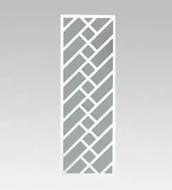
Astonished Pattern Ready Made Cnc Door Window Frame
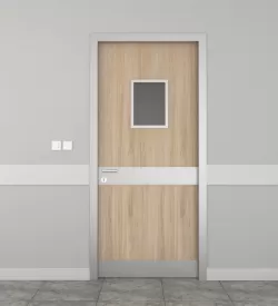
Kazbegi Oak Kick-Resistant Laminate Hospital Door
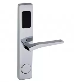
Este Novita Card Reading Hotel Door Lock

Akça Oak 30-Minute Fire-Resistant Hotel Door

Avangard Rondo Hotel Lock with Card Reading

Carpathian Ash Tree Aluminum-Framed Hospital Door

Red Calla Lily Glass and Stretcher-Compatible Laminated Hospital Room Door

Atlantis 30-Minute Fire Certified Card Lock Compatible Hotel Door
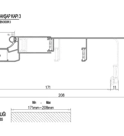
17-20cm Adjustable Aluminum Door Frame

Montana 30-Minute Fire-Resistant Hotel Door
- Blog Comments